The wireless PV reference sensor
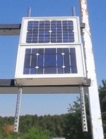
The first device we decided to build after the feasibility test was the wireless photovoltaic reference sensor. This system does not measure the PV module we want to get the I-V curve, instead, it perform measurements on two other different calibrated solar cells whose purpose is to provide an accurate measurement of the irradiance and the temperature. These values are required later to perform the extrapolation of the I-V curve to the STC conditions according to the Spanish norm UNE-EN 60891.
Functional requirements
Before the design of the device itself, the researchers had to establish the minimum requirements the design must perform. The proposed device must:
- Measure the open-circuit voltage value of a calibrated solar cell that will provide the value of the cell temperature.
- Measure the short-circuit current value of a calibrated solar cell that will provide the value of the solar irradiance. Note that this will be performed with a shunt resistor to turn the current into a difference of voltage that is what is actually measured.
- Be able to communicate with the PV analyzer using radio signals to send the data measured at a proper frequency and distance.
- Be an autonomous device, with its own power supply.
- Minimize the energy consumption, to increase the lifetime.
- Provide accurate, precise and repeatable measurement results.
- Be small in size.
- Be light in weight.
- Be low in cost.
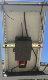
- Include the entire required elements in an enclosure that protects them from the environment and possible accidents.
The first time the requirements were established, there were some more that ended up being deleted as they didn't really make sense, as a result the design of the reference device became more simple and cheaper. These requirements eliminated were:
- Measurement of the temperature of the reference box to prevent the electronics and the battery from overheating. Although this was an important feature at the beginning, it turned out to be not so useful. This is because if we place the reference box behind the solar cells, it will not overheat, and it is really difficult that it reaches the 85 degrees Celsius required to damage the electronics used in the device.
- Storage of the information on an SD card device. Once again, this didn't really make sense in this project, as there is no point of storing a lot of data about the irradiance and temperature unless you need them for a specific use.
- Real time clock. Since the storage of the data is performed in the PV analyzer it makes sense to add this feature in that specific device and not in both of them.
Hardware components
This section of the document aims to list and describe the elements used in the design of the PV reference sensor. The components used are:
- A calibrated solar cell used to measure the temperature of the cell. To perform this task it will require having their terminals open.
- A calibrated solar cell used to measure the irradiance that reaches the solar cell. To perform this task it will require having their terminals closed. Note that one panel requires the circuit to be open and the other need to be closed, thus we need to two different solar cells to measure both magnitudes.
- A calibrated shunt resistor is required to turn the short circuit current of the calibrated panel into a voltage difference signal that can be measured on the Arduino ADC. In this case the relation of the shunt resistor was 4A = 150mV.
- An Arduino UNO board.
- An Arduino compatible Wireless shield . Used to send the measurements to the PV analyzer using radio signals under the Zigbee protocol. It includes an Xbee antenna.
- A customized protoshield compatible with the Arduino UNO board. This board is used to hold all of the electronics and their respective wiring to make it fit in a small space. The elements soldered on it include a voltage divider for the temperature signal, an operational amplifier INA114AP for the irradiance signal (including the resistances for the gain and the supply voltage capacitors), a DC-DC converter with dual output to feed the operational amplifier, a voltage divider to measure the state of charge of the battery, connectors, wiring and headers.
- A lithium-ion battery, used as the main power supply for all of the electronics. It uses 12V and has a rated capacity of 4800 mAh. A capacity test was made to check the actual capacity of the battery. The result was a capacity of 3200 mAh. Although it is a value much lower than the rated value, it seems to be a very good one. It includes its own charger, and has different wires for power supply and charging.
- A LED emitter.
- An on-off switch, a push button, wires, connectors, banana plugs.
- A DIN rail structure to hold everything together and a DIN adapter that is attached at the bottom of the box.